Object Constraints
The Constraints tab in the Physics palette allows you to configure one of three different types of constraints for your physics objects. It also features painting tools that allow you to paint vertex maps that determine how the object responds to physics.
To add a constraint to the currently selected physics object, click the New button in the Constraints tab. You’ll see a menu that allows you to choose one of several constraint types. These are:
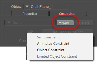
Creating a new constraint
- Self Constraint: Defines how the object responds to physics calculations. Each object can have only one self-constraint. After you add a self-constraint, all vertices are initially set to fully dynamic. Use the vertex painting tools to constrain the vertices that you paint.
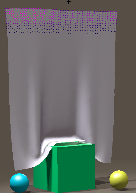
Self Constraint with painted vertices on a cloth plane.
- Animated Constraint: Allows you to use a handle to animate an object. The handle can be assigned as a child of any other object in your scene, or animated in any way you choose. The handle serves as a transform that you can move things around with. The handle will pull on the vertices that you paint. To configure an animated constraint:
- Position the animated handle where you want it to appear. Generally, the handle should be positioned near the object that you are adding the animated constraint to.
- Press the Set Handle Position button.
- Use the painting tools to constrain selected vertices to the animated handle.
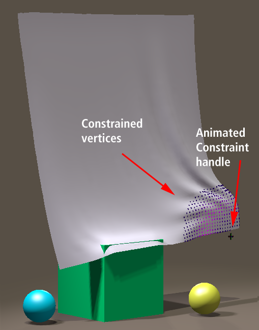
Animated Constraint handle with constrained vertices.
- Object Constraint: Constrains one object to another so that they move together. You use a handle to define the point at which the two objects are supposed to connect to each other, and tries to keep both objects connected at that point. For example, if you have two rigid boxes, named Box 1 and Box 2, that you want to connect together at a certain point:
- Select Box 2, and click the New button in the Constraint tab to create an Object Constraint for this object.
- For the Constrain To object, select Box 1.
- Position the handle at the point where you want to connect the two objects.
- Click the Set Handle Position button after you position the handle.
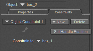
Setup for an Object Constraint.
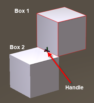
Set Handle Position.
You can chain multiple items together in this manner. For example, you can add another object (such as a third box), and then create another Object Constraint that links Box 3 to Box 2.
Soft bodied objects may drift away from the handle during simulation. Adding a second Object Constraint between the same two objects may improve performance.
- When you click the Live Simulation or Calculate Simulation button you should see your objects moving together. For example, you can drag Box 1 around, and Box 2 will automatically follow it.
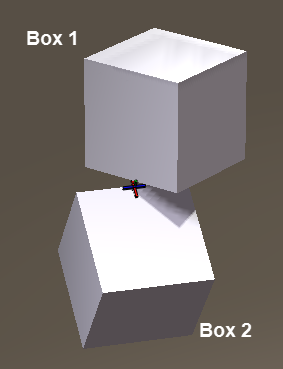
Move Box 1 and Box 2 will follow it.
- Limited Object Constraint: Constrains one rigid object to another so that they move together, and also allows you to limit rotation or translation in the X, Y, and/or Z direction. The Limited Object Constraint can only be applied to a Rigid Body object. Again, you have two rigid boxes, named Box 1, and Box 2. You want them to connect together at a certain point, but you want to limit the rotation of Box 2 to the Z axis:
- Select Box 2, and click the New button in the Constraint tab to create a Limited Object Constraint for this object.
- For the Constrain To object, select Box 1.
- Position the handle at the point where you want to connect the two objects. (The result should look similar to the setup shown previously for the Object Constraint.)
- Click the Set Handle Position button after you position the handle.
- The lower section allows you to set the limits for the X, Y, or Z translations and rotations. In this example, we want to allow rotation only on the Z axis. The X and Y axis rotations are set to 0 minimum and maximum.
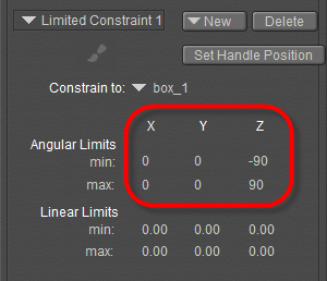
Limiting rotations to the Z axis only.
- When you click the Live Simulation or Calculate Simulation button you should see your objects moving together, with the translations or rotations set as you configured for the Limited Object Constraint. In our example, you can drag Box 1 around, and Box 2 will automatically follow it but the rotation will be limited to the Z axis.
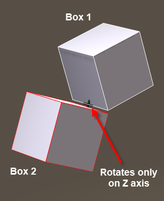
Move Box 1 and Box 2 will follow it with limited rotations.
Painting Constraints
After you set up one of the constraint types mentioned in the previous section, you can use the paintbrush tool to paint a vertex map that defines how the object will respond to that constraint type.
Paintbrush tool.
After clicking the Paintbrush icon, the Dynamics Weights palette opens. This palette allows you to paint the vertices on the object to control how they will be affected by the physics engine. As you paint, the vertices are coded with various colors.
- Where no color appears, the object will be 100% affected by the dynamics in the physics calculations.
- Where color appears, darker colors define areas that will be affected by dynamics the most; brighter colors will define areas that will be less affected.
- Green areas define areas that will not be affected by the physics calculations.
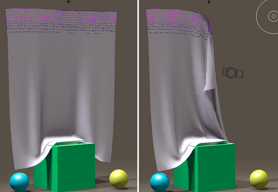
Cloth plane with self constrained vertices fully (left) and partially (right) across the top.
The Dynamics Weights palette contains the following sections and settings:
Initially, all vertices of an object are set to fully dynamic unless you check the Invert Colors option mentioned below.
- Painting Modes section: Choose one of the following painting modes for your dynamic weights paintbrush:
- More dynamic: Select this painting mode when you want to make the object more responsive to physics calculations. Vertices will appear with no color when they are fully dynamic.
- More constrained: Select this painting mode when you want to paint areas on an object to reduce the amount of response to physics calculations. Vertices will appear as bright green when vertices are fully constrained, and the object will retain its base shape in those areas.
- Smooth: Choose this painting mode when you want to smooth or blend transitions between areas that are more dynamic and areas that are more constrained.
- Weight: Choose this painting mode when you want to paint with a predefined strength value. Enter the desired value in the Weight field that appears beneath the option.
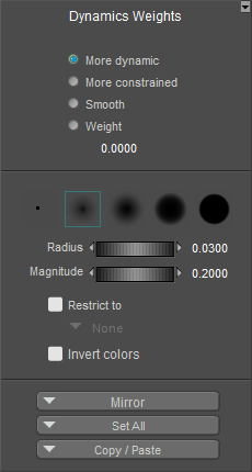
Dynamics Weights Palette.
Deleting Constraints
To delete a constraint, follow these steps:
- From the Object menu in the Physics Simulation palette, select the object that contains the constraint you want to delete.
- Switch to the Constraints tab, if necessary.
- Select the constraint that you want to delete from the list of available constraints (which appears just above the paintbrush).
- Press Delete to delete the selected constraint.