Kitty1 Base Textures-Physical
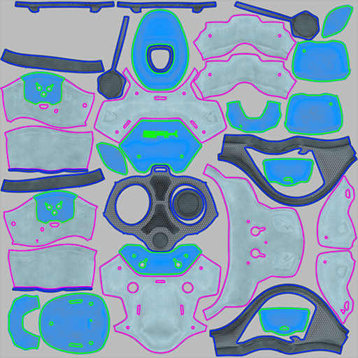
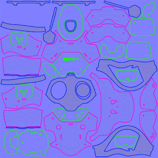
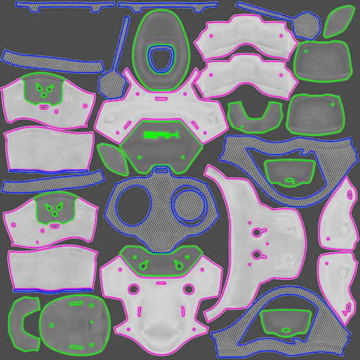
The material zones included in the "Kitty1" maps are as follows. These materials do not need any additional maps such as Opacity, Metallic, or Emission. The outline colors shown in these examples are not actually in the texture maps themselves, they are only used here to help identify the different materials that the maps affect.
- BodyColor1 (Associated Polygons Outlined in Blue for clarity): - Hexagon Pattern
- BodyColor2: (Associated Polygons Outlined in Pink for clarity) - Soft Denim
- BodyColor3: (Associated Polygons Outlined in Green for clarity) - Matte Plastic
| Color Map | Normal Map | Roughness Map |
 |
 |
 |
Start by loading the Kitty from the Poser library:
- Create a new scene in Poser. Delete the default La Femme figure.
- Navigate to the Figures > Included > Toys character library and add SA Kitty Mass Production to your scene.
- Adjust the camera so that you can view the character more closely.
- From the Materials library, navigate to the Materials > Included > Toys > SAKitty Tutorial library. Click the single checkmark to apply the !All White material to the kitty. All of the materials in the kitty will change to white, giving you a good place to start adding your materials.
The textures for the kitty are arranged in three UV tiles, with texture names starting with SAKitty1, SAKitty2, and SAKitty3. To assign the first set of textures, follow these steps:
- Switch to the Material Room. With the SAKitty object selected, choose the BodyColor1 material in the Edit tab.
- Right-click in an empty area in the Edit pane, and choose New Node > Root > Physical Surface. This adds a Physical Surface node to the editor.
- Check the FireFly Root and SuperFly Root checkboxes at the top of the Physical Surface node.
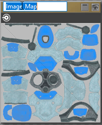
- You can add three image map nodes in one of two ways:
- Open Windows Explorer or the Mac Finder to the Included > Runtime > Textures > SAKitty Tutorial folder, and drag and drop the SAKitty1_Color, SAKitty1_Normal, and SAKitty1_Roughness maps into the Edit window. This automatically creates three Image Map nodes with the textures loaded into them.
- Right-click in the Edit window, and choose New Node > 2D Textures > image_map, then choose one of the above-mentioned textures to load in the image node. Repeat for the other two textures.
- Change the name of each of the image map nodes to reflect the type of image being used:
- Change the name of the Color map to Color
- Change the name of the Roughness map to Roughness
- Change the name of the Normal map to Normal
Changing a Texture Name
- For the Color texture, set the Filtering option in the Image Map node to Crisp. Connect the output from the Color image map node to the Color input of the Physical Surface node. Then set the color chip input in the Physical Surface node to pure white (it is slightly off-white by default). If desired, collapse the image map node so that only the texture preview shows.
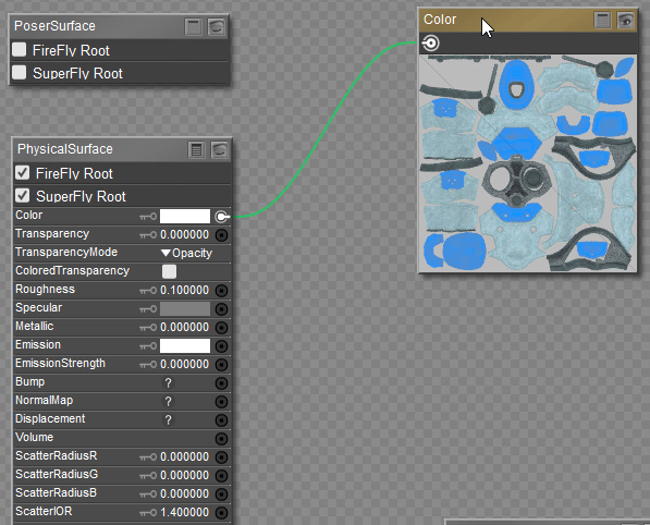
Connecting the Color Map
- For the Roughness texture, set the Filtering option in the Image Map node to Crisp. Click the Image_Source field to open the Texture Manager, and set the Custom Gamma value to 1.0. Connect the output of the Roughness map to the Roughness input of the Physical Surface node, and change the Roughness input value in the Physical Surface node to 1.
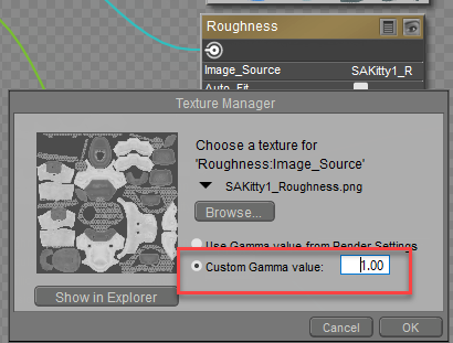
Set Custom Gamma to 1 for Roughness image map.
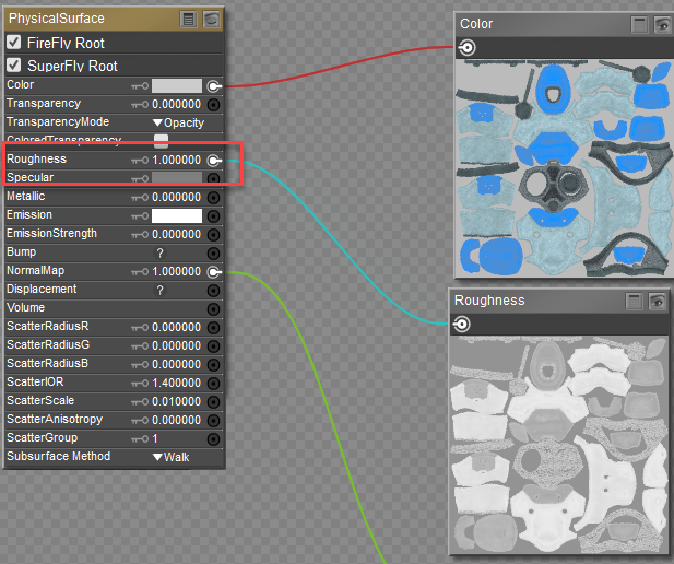
Roughness connection and setting
- The changes that you need to make for the Normal map are similar to those you made for the Roughness map. First, set the Filtering option in the Image Map node to Crisp. Click the Image_Source field to open the Texture Manager, and set the Custom Gamma value to 1.0. Connect the output of the Normal map to the Normal input of the Physical Surface node. The setting of the Normal map should remain at 1 (which is the default value). Changing this value will cause the normal map to preview incorrectly.
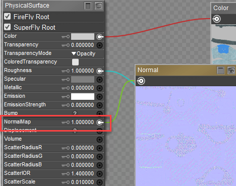
Connect the Normal map to the Normal input of the Physical Surface Node. Leave setting at 1.
- Right-click an empty space in the Edit window and choose Select All to select all of the nodes. Then right-click again and choose Copy to place them in your clipboard.
- Select BodyColor2 from the Materials list above the Edit window. Right-click to select the contents that are already there, and choose Replace to paste the contents from the clipboard.
- Repeat step 10 for BodyColor3. Now all of your connections for the first set of textures are complete.
- Continue to Kitty2 Base Textures-Physical.
Attaching Bump Maps to the Physical Surface Node
If you want to use bump maps instead of, or in addition to, normal maps the process is similar to the above.
- Create an image map node, and assign the bump map texture to it.
- In the Texture Manager, set the Gamma value to 1.
- Set the Filtering option in the Image Map node to Crisp.
- Connect the output of the Bump map to the Bump input of the Physical Surface node.
- Set the Bump Strength to a value that is appropriate for your bump map. Moving in close to your object and doing frequent area renders of small areas will help you determine the best setting for your bump maps.
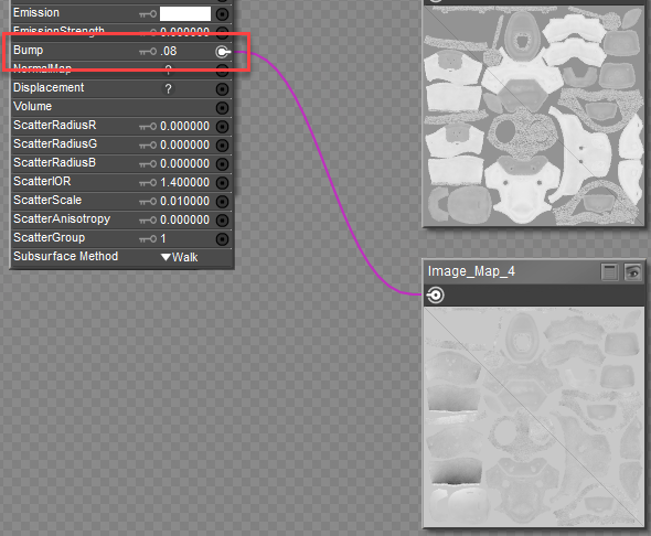
Connect the Bump map to the Bump input of the Physical Surface Node. Adjust strength value as needed.