Angle Measurements
Angle measurements allow you to determine an angle between two lines that meet at a center point.
To create an angle measurement, follow these steps:
- Choose Object > Create Measurement > Create Angle, or click the Measurement Mode icon in the bottom right corner of the document window and select Create Measurement - Angle.
- Click the first point to set the end point of the first line in the angle (point 1 in the figure below, which picks one of the back legs of the chair).
- Click the second point to set the point at which the two lines in the angle will connect (point 2 in the figure, which selects one of the points on the oil can).
- Click the third point to set the end point of the second line in the angle (point 3 in the figure, which selects one of the corners of the cinder block).
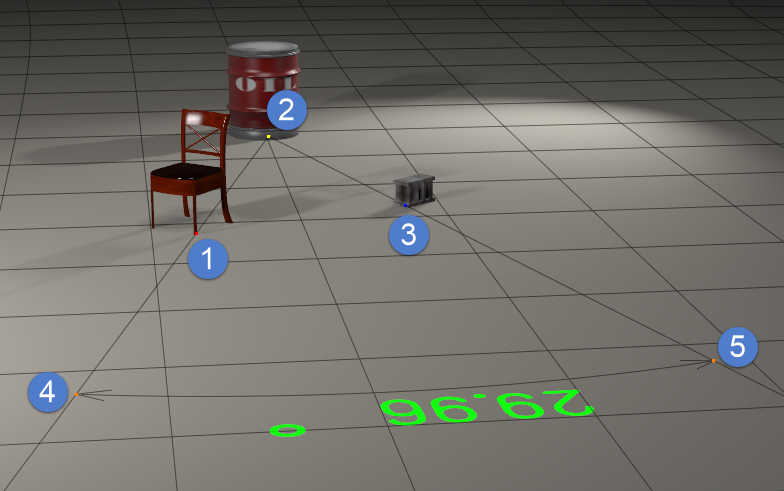
Angle measurement object.
- To adjust an angle measurement (reference the above figure):
- After your angle measurement is complete, the first point you clicked will be colored red, the second will be yellow, and the third will be blue.
- Hover your mouse and then drag at points 1 (red) or 3 (blue) to adjust the measurement point for each of the arms in the angle.
- Hover your mouse and then drag at point 2 (yellow) to select a new common point for the angle.
- Hover your mouse and then drag at points 4 or 5 (orange) to adjust the distance that the measurement extends from the measurement points. You can also control the scale of the extension line using the Extension Line Scale dial in the Parameters Palette.
- If you move any of the objects that contain a measurement point, the text object will update to display the new angle as you change the positions of the objects.
- You can set the following properties for an angle measurement in the Properties palette:
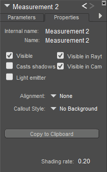
Angle measurement properties.
- Name: Enter a name that describes the measurement you are creating.
- Visible: Turns display of the measurement indicator on or off. Keep this option checked to view the angle measurement while you are creating it.
- Visible in Raytracing: Checking the Visible in Raytracing checkbox makes the measurement object visible in raytraced reflections, such as when the figure is in front of a mirror. Clear this checkbox to make the measurement object not appear in reflections.
- Casts Shadows: Checking the Cast Shadows checkbox forces the selected measurement object to cast a shadow that is visible in your scene. Clear the checkbox to cast no shadow.
- Vislble in Camera: When checked, the measurement object is visible in the camera and in the final render. When unchecked, the object does not render.
- Light Emitter: When checked, allows the object to be included in indirect lighting calculations so that light will bounce off the object. When unchecked, indirect lighting calculations are skipped for the object.
- Alignment: By default, the measurement will not be aligned to any axis (None). Options in the Alignment menu allow you to align the measurement to the X, Y, or Z axis.
- Callout Style: Allows you to display measurement text without a background (default), or against a black background.
- Copy to Clipboard: Click this button to copy the measurement dimension into your clipboard to paste into another document.