Parts of the Joint Editor
The Joint Editor displays the various components of the selected joint. For example, if you have the right shin selected, the Joint Editor will display the settings related to the knee (the point at which the right shin begins).
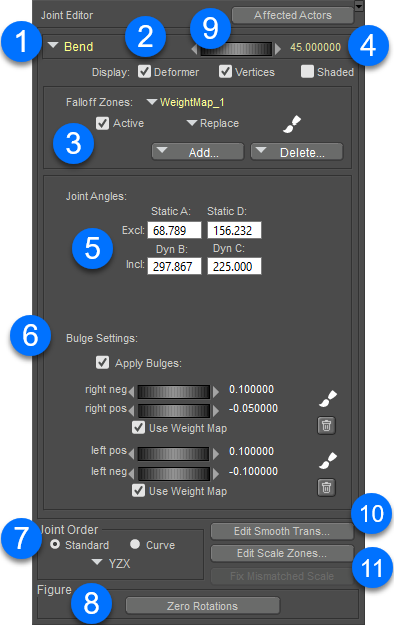
The Joint Editor displays the following options and controls, depending on the joint that you have selected:

The Joint Editor.
- Attribute selector (1): Use the Attribute selection menu to display and edit the settings for a specific attribute. For example, when you have the right shin selected, you can use the menu to choose one of the following attributes: Center, Twist, Side-Side, or Bend. In addition, there will be a couple of additional settings that relate to the body part that is immediately below the current part (its child). In the case of the right shin, the child attributes would relate to the right foot. In most cases, the attributes for the “child” part are left alone when editing the current joint.
- Display Options (2). Allows you to show or hide various display options for the selected transform:
- Deformer: When checked, will display the deformers (if any) that are associated with the selected joint.
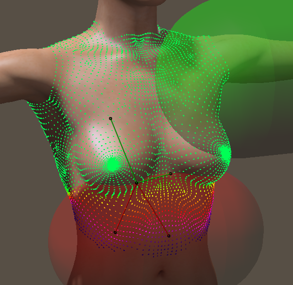
- Verts: Shows or hides the display of colored dots that give you a visual indication of how the vertices and polygons will be affected when you adjust the joint settings.
- Shaded: Enables shaded display mode for sphere or capsule zones of influence. Inner mat spheres or capsules are shaded green, and outer mat spheres or capsules are shaded red.

A chest joint with verts and shaded display.
- Falloff Zones (3): There are three types of falloff zones: Spherical Zone, Capsule Zone, and Weight Map. Each of these will be described in Creating and Using Falloff Zones.
- Parameter dial and value (4): When you choose an attribute that has a Parameters dial associated with it, a dial will appear in the Joint Editor. You can use this dial to adjust the parameter through its minimum and maximum values to test how the current joint settings affect the mesh.
- Joint Angles setting (5): This section displays or edits the inclusion and exclusion angles, which determines which vertices and polygons are included or excluded in the current transform. Further information can be found in Setting Joint Angles.
- Bulge Settings (6): Allows you to add additional settings that specify how polygons bulge and flex while the joint is moved. See Editing Bulge Settings.
- Joint Orders (7): Allows you to set the order of the X, Y, and Z axes, and the types of rotation that they relate to. See Setting Joint Orders.
- Zero Rotations button (8): As you are working with all of the joints in your figure, you may have one or more rotations (bend, twist, side to side, and so on) set to values other than zero. Click this button to return all of the joint rotations back to their zero values, which returns the figure to its normal “default” position.
- Affected Actors menu (9): Use this menu to select additional body parts that you want to be affected by the parameter that you are editing. For more information about affected actors, see Adding Affected Actors.
- Create Smooth Trans: Click this button to create smooth transition zones that blend between translated body parts. For more information see Smooth Translation Bending.
- Edit Scale Zones (11): Click this button to create weight maps that smooth out the transitions between joints when the joints are scaled along a single axis. For more information, see Smoothing Scale Zones.